Tel:
Tel: E-Mail:
 English
 Chinese
 한국어
한국어
 Español




News
Pneumatic Butterfly Valves for Industrial Automation: Air Consumption, Torque Charts, and Positioner Setup
In industrial automation—think chemical processing, pharmaceutical mixing, or heavy slurry lines—electric actuators sometimes fall short. Pneumatic butterfly valves offer faster cycling speeds, higher fail-safe reliability, and safer operation in explosive or high-humidity environments.
This guide covers pneumatic actuator sizing, air consumption calculations, positioner configurations, and installation standards for automated process control.
Why Pneumatic Butterfly Valves for Industrial Automation?
Compared to electric or manual alternatives, pneumatic valves excel in demanding industrial settings:
High Cycle Rates: Up to 3-5 operations per second without overheating.
Explosion-Proof: No electrical arcing; safe for Class I Division II environments.
Fail-Safe Action: Spring-return actuators close automatically on air loss.
High Torque Output: Lower actuator weight compared to electric for same torque.
Technical Specifications
| Parameter | Specification |
|---|---|
| Size Range | DN25 to DN800 (1” to 32”) |
| Body Material | Cast Iron / Ductile Iron / Stainless Steel 316 / PVC |
| Disc Material | CF8M (316 SS) / Duplex / PTFE-coated |
| Seat Material | EPDM / Viton / PTFE / NBR |
| End Connection | Wafer / Lug / Flanged |
| Actuator Type | Double-Acting or Spring Return |
| Operating Pressure | 4 to 8 Bar (60 to 120 PSI) |
| Media Temp Range | -20°C to +200°C (depending on seat) |
Pneumatic Actuator Torque Chart
Selecting the wrong actuator results in valve sticking or seat damage. Below is the recommended torque output at 6 Bar (90 PSI).
| Valve Size (DN) | Max Break Torque (Nm) – Seat Friction | Recommended Double-Acting Actuator | Recommended Spring Return Actuator |
|---|---|---|---|
| DN50 | 30 Nm | DA-52 | SR-52 (Spring close) |
| DN80 | 50 Nm | DA-63 | SR-63 |
| DN100 | 80 Nm | DA-75 | SR-75 |
| DN150 | 150 Nm | DA-88 | SR-88 |
| DN200 | 250 Nm | DA-100 | SR-100 |
| DN300 | 500 Nm | DA-125 | SR-125 |
| DN400 | 900 Nm | DA-160 | SR-160 |
Critical Note: Break torque (initial movement) is 1.5x running torque. Always add 20-30% safety margin for pressure spikes.
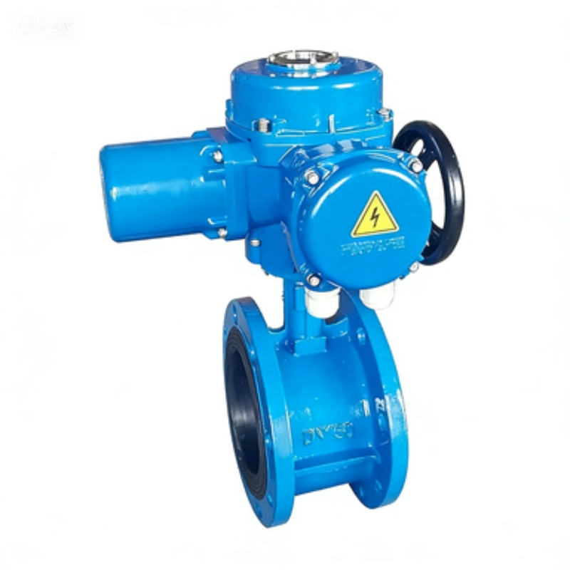
Air Consumption Table (Per cycle – liters)
For compressor sizing, calculate air consumption per valve operation (open + close).
| Actuator Size | Double-Acting (L/cycle) | Spring Return – Air to open (L/cycle) |
|---|---|---|
| DA-52 / SR-52 | 1.2 L | 0.8 L |
| DA-63 / SR-63 | 2.5 L | 1.5 L |
| DA-75 / SR-75 | 4.8 L | 2.8 L |
| DA-88 / SR-88 | 8.2 L | 4.5 L |
| DA-100 / SR-100 | 13.5 L | 7.2 L |
| DA-125 / SR-125 | 25.0 L | 13.0 L |
| DA-160 / SR-160 | 48.0 L | 25.0 L |
Compressor sizing formula: Total L/min = (Cycles per hour ÷ 60) x Air consumption per cycle x Number of valves
Positioner Selection Matrix
Industrial automation requires precise positioning. Choose the right positioner type for your control loop.
| Positioner Type | Input Signal | Accuracy | Best For |
|---|---|---|---|
| Analog (I/P) | 4-20 mA | ±2% | Basic modulating control |
| Digital (Smart) | 4-20 mA + HART | ±0.5% | Critical flow control, diagnostics |
| Fieldbus | Profibus / Foundation Fieldbus | ±0.5% | Fully automated plants (DCS) |
| Mechanical Limit Switch | Dry contact | On/Off only | Simple open-close applications |
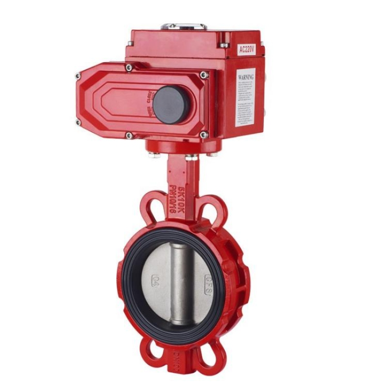
Recommended Settings for Common Media
| Media | Recommended Seat | Positioner Action | Fail-Safe |
|---|---|---|---|
| Water / Glycol | EPDM | Linear or Equal % | Close on air loss |
| Steam | PTFE / Metal-seated | Linear | Close on air loss |
| Acidic Chemicals | Viton | Quick opening | Open on air loss |
| Abrasive Slurry | Hard-lined (UHMWPE) | Slow opening (anti-hammer) | Close on air loss |
Installation Best Practices for Pneumatic Valves
Air Supply Quality: Use air filter regulator with 5-micron filtration. Water or oil in air lines destroys positioner internals.
Solenoid Valve Mounting: Mount 3/2 or 5/2 way solenoid valves directly on NAMUR interface—no external tubing required.
Tube Sizing: For actuator sizes DA-100 and above, use 1/4" (6mm) minimum tubing; for DA-125+, use 3/8" (10mm).
Spring Return Direction: Always verify whether spring is set for "air to open" (fail closed) or "air to close" (fail open) before installation.
Limit Switch Calibration: Set open/close cams at 0° (closed) and 90° (open). Over-travel beyond 92° damages the disc seal.
Common Automation Applications
| Industry | Application | Valve Size Range | Required Feature |
|---|---|---|---|
| Chemical Dosing | Acid transfer | DN25 – DN80 | PTFE seat, Viton seals |
| Food & Beverage | CIP return lines | DN50 – DN150 | 316L stainless, EPDM FDA-grade |
| Water Treatment | Sludge recirculation | DN100 – DN300 | Heavy-duty disc, SS shaft |
| Pharmaceutical | Sterile filling | DN25 – DN65 | Electropolished, sanitary clamp |
| Power Plant | Cooling water bypass | DN200 – DN600 | Lug type, replaceable seat |
Troubleshooting Quick Guide
| Symptom | Possible Cause | Fix |
|---|---|---|
| Valve does not stroke | No air pressure, bad solenoid | Check supply pressure (min 4 Bar) |
| Sluggish operation | Low air flow, clogged filter | Clean filter, increase tube size |
| Positioner hunting (oscillation) | Actuator too large, or friction too low | Add volume booster or reduce positioner gain |
| Leakage at shaft | Disc stem seal worn | Replace V-ring packing set |
| Valve does not seal fully | Disc or seat debris | Cycle valve 3-4 times to clear debris |
Ivan (Mobile:+86-18968769287)
WhatsApp:+86-13579991606
Wechat:+86-18968769287
Website:www.kinko-flow.com
ZHEJIANG KINKO FLUID EQUIPMENT CO.,LTD

 info@kinko-flow.com
 +86-133 5611 9006