Tel:
Tel: E-Mail:
 English
 Chinese
 한국어
한국어
 Español




News
What Is a DCS and Why Does Integration Matter?
A Distributed Control System is a networked platform that centralizes process control across a plant. It receives input from sensors, executes control algorithms, and sends output signals to actuators and valves.
For a control valve with an electric actuator, DCS integration means:
Sending a setpoint signal to the actuator (position command)
Receiving real-time position feedback from the valve
Monitoring valve status (open/closed, fault, alarms)
Enabling remote calibration and diagnostics
Supporting alarm and interlock logic
Reliable integration ensures the valve responds accurately to process demands, enhancing product quality, safety, and energy efficiency.
The Signal Chain – From DCS to Valve
The typical signal flow for an electric actuator controlled by a DCS follows this path:
| Step | Component | Signal Type |
|---|---|---|
| 1 | DCS controller | PID algorithm generates output |
| 2 | DCS output card | 4–20mA or digital bus signal |
| 3 | Control room to field | Wired cable (analog or digital) |
| 4 | Electric actuator | Receives command signal |
| 5 | Actuator motor | Positions valve accordingly |
| 6 | Feedback sensor | Measures actual position |
| 7 | Actuator output | 4–20mA or digital feedback to DCS |
| 8 | DCS input card | Reads position for display and control logic |
The most common control signal is 4–20mA, with 0–10V also used in some applications. Increasingly, digital fieldbus protocols are being deployed for richer data exchange.
Analog Integration – 4–20mA and 0–10V
4–20mA Loop
4mA = 0% position (fully closed)
20mA = 100% position (fully open)
Two-wire or four-wire connection
Long-distance capable (up to 1000m)
Fault detection: <4mA or >20mA indicates loop break
0–10V Signal
0V = 0% position
10V = 100% position
Three-wire connection
Shorter distance (susceptible to voltage drop)
No inherent fault detection
For most industrial DCS applications, 4–20mA is preferred due to its noise immunity and loop diagnostics capability.
Digital Integration – Fieldbus Protocols
Digital communication offers bidirectional data exchange, including position, status, diagnostics, and configuration parameters.
| Protocol | Features | Common in |
|---|---|---|
| HART | Hybrid analog+digital; 4–20mA plus digital overlay | Chemical, oil & gas |
| Modbus RTU/TCP | RS-485 or Ethernet; multi-drop | General industrial, building automation |
| Profibus PA/DP | Digital only; power over bus | Process automation, European plants |
| Foundation Fieldbus | Digital only; device-level control | Large process plants, refineries |
| BACnet MS/TP | Building automation protocol | HVAC, building management |
| EtherNet/IP | Industrial Ethernet | Manufacturing, packaging |
HART is the most common retrofit-friendly solution, as it works over existing 4–20mA wiring.
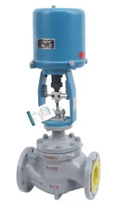
Integrating KK Series Electric Actuators with DCS
Our KK Series electric actuators support multiple integration methods to suit various DCS architectures.
| Integration Type | KK Series Capability |
|---|---|
| 4–20mA modulating | Standard on modulating versions (position command + feedback) |
| 0–10V modulating | Optional |
| On/Off (discrete) | Dry contacts for open/close commands via DCS digital outputs |
| Position feedback | 4–20mA or potentiometer (0–1kΩ) |
| Limit switch feedback | Open and closed dry contacts to DCS digital inputs |
| Modbus RTU | Optional communication module |
| BACnet MS/TP | Optional for building automation |
| HART | Available via external converter or optional board |
Wiring and Termination – Key Considerations
Proper wiring is essential for noise-free DCS integration.
| Wiring Element | Recommendation |
|---|---|
| Signal cable | Shielded twisted pair for analog signals |
| Cable length | 4–20mA: up to 1000m; 0–10V: keep <100m |
| Grounding | Single-point ground to avoid ground loops |
| Termination | Use shielded connectors; terminate shield at DCS end |
| Isolation | Use galvanically isolated output cards to prevent ground loops |
| Power supply | Separate power for actuator and signal circuit recommended |
Setting Up the Actuator for DCS Control
Typical steps for configuring a KK Series electric actuator for DCS integration:
Wire the control signal to actuator terminals (4–20mA or 0–10V)
Wire feedback signal from actuator to DCS input card
Set DIP switches for signal type (mA/V) and action direction (direct/reverse)
Calibrate the actuator zero and span to match DCS signal range
Perform a full stroke test from DCS and verify feedback reading
Adjust PID parameters in DCS if needed (gain, integral, derivative)
Test fault conditions (signal loss, over-torque) to confirm alarm handling
Position Feedback – What the DCS Needs to See
Feedback enables the DCS to:
Confirm valve reached the setpoint
Detect sticking or slow response
Trigger alarms on deviation
Display valve position on operator screen
Log valve performance for maintenance planning
| Feedback Type | Accuracy | Output Signal |
|---|---|---|
| Potentiometer | ±5% | 0–1kΩ or 0–10V |
| 4–20mA position transmitter | ±1% | 4–20mA |
| Absolute encoder | ±0.5% | Digital (Modbus, etc.) |
| Limit switches (discrete) | Open/closed only | Dry contact |
Diagnostics and Predictive Maintenance via DCS
Modern digital actuators can send diagnostics that the DCS can use for predictive maintenance:
Torque / current profile – indicates increasing friction or seat wear
Cycle count – tracks usage for maintenance scheduling
Stroking time – increases may indicate mechanical issues
Temperature – actuator overheating alerts
Power interruptions – logged for reliability analysis
With KK Series actuators supporting Modbus or external HART, these diagnostic data points can be transmitted to asset management systems within the DCS environment.
Common DCS Integration Issues and Solutions
| Issue | Cause | Solution |
|---|---|---|
| Valve does not reach setpoint | Signal mismatch (mA vs V) | Check DIP switch setting |
| Feedback reads wrong | Zero/span not calibrated | Re-calibrate actuator |
| Signal noise or jitter | Unshielded cable / ground loop | Use shielded cable; isolate grounding |
| No response from actuator | Power supply issue or wiring fault | Check voltage at terminals |
| Actuator oscillates around setpoint | DCS gain too high | Tune PID parameters |
| DCS shows fault but valve works | DCS input card configuration mismatch | Verify input type (mA/V, active/passive) |
Troubleshooting Integration Checklist
When integration fails, use this checklist:
Verify actuator is powered (voltage at terminal)
Check control signal at actuator terminal (4–20mA or 0–10V)
Confirm signal polarity (terminal markings)
Ensure DIP switches match signal type
Check calibration settings (zero and span)
Verify feedback signal reaches DCS input card
Check DCS channel configuration (input type, scaling)
Confirm common ground reference
Test with a signal generator to isolate DCS issue
Integration with On/Off Control vs. Modulating Control
| Feature | On/Off (Discrete) | Modulating (Analog) |
|---|---|---|
| Control signal | Digital (24V DC or dry contact) | 4–20mA / 0–10V |
| Feedback | Open/closed limit switches | Continuous position signal |
| DCS I/O type | Digital output + digital input | Analog output + analog input |
| Accuracy | Position confirmation only | Precise positioning |
| Typical application | Isolation, pump start/stop | Flow, pressure, temperature control |
Frequently Asked Questions
Q1: Can an electric actuator work with any DCS?
Yes – as long as the actuator supports the control signal type (4–20mA, 0–10V, or digital bus) used by the DCS.
Q2: What is the most common signal for DCS integration?
4–20mA is the industry standard for analog process control due to its noise immunity and fault detection capability.
Q3: Do I need a separate positioner for electric actuators?
No – electric actuators have built-in position control electronics, unlike pneumatic actuators which require an external positioner.
Q4: How is actuator calibration done for DCS integration?
Most electric actuators allow zero/span calibration via DIP switches, potentiometers, or digital configuration tools—no external calibrator required.
Q5: Can I connect multiple electric actuators to one DCS communication bus?
Yes – with Modbus, BACnet, Profibus, or Foundation Fieldbus, multiple devices can be daisy-chained on a single bus.
Q6: What happens if the control signal is lost?
Our KK Series actuators can be configured to hold position, go fully open, or go fully closed on signal loss—selectable during setup.
Ivan (Mobile:+86-18968769287)
WhatsApp:+86-13579991606
Wechat:+86-18968769287
Website:www.kinko-flow.com
ZHEJIANG KINKO FLUID EQUIPMENT CO.,LTD

 info@kinko-flow.com
 +86-133 5611 9006